Saturday, March 17, 2018

Weatherproofing a Motorcycle Dash Camera System

I bought a two camera system for my motorcycle to record what was going on in front and behind my motorcycle as a record in the event of an accident, but I wanted to check to see how well protected it would be against water ingress.
Unfortunately, while there was adequate strain relief on the wires, there was no sealing on the enclosure or protective coating on the PCB to prevent water damage.

I applied some brush-on conformal coating to the board before closing the box again and mounting it on my motorcycle. Conformal coating is a good option here because it is easy to selectively apply it to the board while avoiding areas like the microphone and the micro SD card connector (which would be much more difficult to do with a potting material). I also don't have to worry about dealing with CTE mismatch with a conformal coating in the same way that I would with a potting material.

The camera resolution could be better, but the framerate is acceptable and much better than not having anything. Below is a test clip from the evening that I installed it, the night quality could also be better and the audio is terrible (warning before trying to play the video). The timestamp is also incorrect as I hadn't set the time yet.

Fixing the wiring on my 3D printer

I've been reasonably happy with my Solidoodle Press 3d printer, but the wiring harness was not built with any strain relief on the extruder head, which eventually led to a wire for the extruder stepper motor to fail.
Fortunately, I was able to come up with a relatively non-invasive solution by making a bracket to attach some plastic cable drag chain to the head. I did have to re-do the wiring to the head to extend the length out, but the result should be much more durable.

New Workshop Tool: a Free Milling Machine (!)

One of the mechanical engineers I work with was moving and was kind enough to offer his K&F MD-40 milling machine to me and my friends for free as long as we came and took it off his hands for him!
It turns out that moving a "desktop" mill onto a cart is arguably harder than moving a full size mill around, but we figured it out after a few hours.

My friend Ben has put in a lot of time cleaning it up and making it usable, and I've been helping by re-organizing the garage to accommodate the "new" mill

Flea Market Wrench Restoration

I found this beauty of a wrench for $2 at the infamous flea market at De Anza college in the bay area.

It was pretty crusty when I found it, but with a little love with some steel wool it cleaned up pretty well:

A fine addition to my growing wrench collection.

New Phone Holder for Project Pics

Put together a pretty nice clamping arm setup for holding smartphones/cameras for taking pictures/videos of projects. Nobody sold the exact thing that I wanted, so I ordered three separate things from Amazon and put them together. Hopefully this will mean better project pictures in the future!

Items used:
CAMVATE Universal C-Clamp
CAMVATE 360 degree 1/4" Articulating Magic Arm Mount
Vastar Universal Smartphone Tripod Adapter

Wednesday, October 18, 2017

Extracting CAD from PDFs

While creating documentation of a pinout for a project I discovered that what I thought was an image of the connectors for the enclosure I was using actually had a lot more to it than meets the eye.

Source PDF: https://belfuse.com/images/ModICE%20ME-MX.pdf
Tools Used: Foxit PhantomPDF editor, Inkscape, SolidWorks


Selecting the face view that I wanted revealed that this was an object, not a picture. What's more, there were hidden elements to the object:


It turns out that there were three different views of each of the connector options hidden in the object. I wasn't able to do much with the object in PhantomPDF, so I opened the pdf in Inkscape. From there I was able to make all of the items items visible, and copy the object to a new file and export it to a .png, .svg, and most usefully, a .dxf

This was especially useful because the manufacturer didn't have any CAD models of the enclosure on their website. With a DXF it's a straightforward process to import the data into a SolidWorks sketch. Using the dimensions in the 2D mechanical drawings provided, you can scale the DXF to the correct size. You can then reconstruct a 3D model from the sketches


While in this case (no pun intended) you probably could have created a workable CAD model from the 2D drawings by themselves, it is interesting to see how much data can be extracted from a PDF of a product brochure. It is also possible to get a DXF from this PDF even if the connector view was an image using some contour tracing methods, but this would likely take longer and may not produce as good of a result.

Note: Many manufacturers have user agreements that forbid the extraction of data for the purposes of design reconstruction/reverse engineering. This was not the case with this enclosure at the time of this writing. This post should not be taken as an endorsement of such behavior, and is intended for educational purposes only.

Wednesday, April 27, 2016

Hendo 2.0 Hoverboard

In July of 2015 I started work as the only electrical engineer at Arx Pax, a startup company that makes real hoverboards using magnetic levitation(!!!). It was as much fun and work as you think it would be.

There was a ton of different projects that I worked on there, but the coolest one has to be the Hendo 2.0 hoverboard. For obvious reasons (read: NDA) I can't really talk about this project with the depth that I normally do. Suffice it to say that designing a hoverboard comes with the same challenges that electric vehicle design does.


Our big release event happened on October 21st, 2015-- the same date that Marty McFly travels to and rides a hoverboard in Back to the Future II. I naturally had to wear a Marty McFly costume complete with light up shoes and jacket signed by Back to the Future writer Bob Gale.


I've since moved on to start working at Farasis Energy to work with my good friend Jackson aka Farfle to work on lithium batteries for electric vehicles and other cool stuff. I had a blast working on this project and with the awesome engineering team at Arx Pax, and think that "Hoverboard designer" may have a permanent place on my resume ;)

Since the event there have been some cool videos that have come out that you can check out:
Wired Video and Article about the Hendo 2.0
CNET's Hendo 2.0 Video

Beerpong Robot

Final Results
At the end of our 10 week robotics class we had a robot that could play beerpong! We placed third at the competition, losing to Team 12: "The Hammer" (1st place) in the quarter-finals and then to Team 7: "ZZZZ Best" (2nd) in the sixth or seventh lightning round of the semi-finals.
The robot performed fairly well minus a few software issues mainly related to IR sensor threshold values used for detecting the ping pong ball's position when reloading not suitable for the outdoor sun and lightning round code that was written hastily and not designed to run for multiple rounds without restarting the robot.


The final loading mechanism used a motorized sleeve that acted as a "sealed" door to keep the airflow through the tube more consistent.


You can watch the video below to see how it performs. We also added a defensive ball swatting unit with an Arduino Uno a couple of days before the competition. It used a speaker taped to the bottom of the playing table as a microphone input and would swing the flyswatter back and forth a few times whenever it detected a ball hitting the table. It was surprisingly effective, and the signal response for a ball hitting the table was much higher than any ambient noise that we didn't have any false triggers furing gameplay.


Wiring Diagram
We chose to use Fritzing to do the wiring diagram for the robot to keep things straight when working on everything (it got to be a bit of a ratsnest sometimes)

Robot GUI
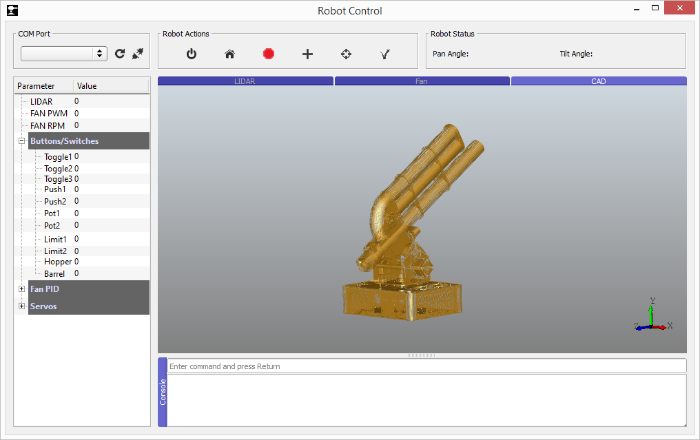
The GUI was written in Python and allowed for control of the robot and for displaying data from the various sensors such as the LIDAR and the tachometer for the fan.
There was work for a feature that would display a 3D model of the robot using pythonocc that would adjust the pan and tilt angle to match the robot to make remote control easier.
While we were able to open and view a STEP file of the robot, we took the feature out of the program before it was finished due to a lack of time.

Monday, May 11, 2015

Beerpong Robot Update 5/11/2015

After spending a lot of time wiring and rewiring the robot, we are getting closer to being completely out of "hardware mode" and can spend more time on the software end of things.

We've added some sensors to the loading system for detecting the position of a ping pong ball, which has made the loading process much more simple to code.


We've also started working on a GUI for displaying data from the robot and controlling it remotely using Python and PyQt.


There's still definitely a lot more work to be done, but things are coming together well right now.

Monday, April 27, 2015

Beerpong Robot Update 4/27/2015

We have been hard at work on the Beerpong robot for my Applied Robotics Class and have gone through a couple of changes in the design.

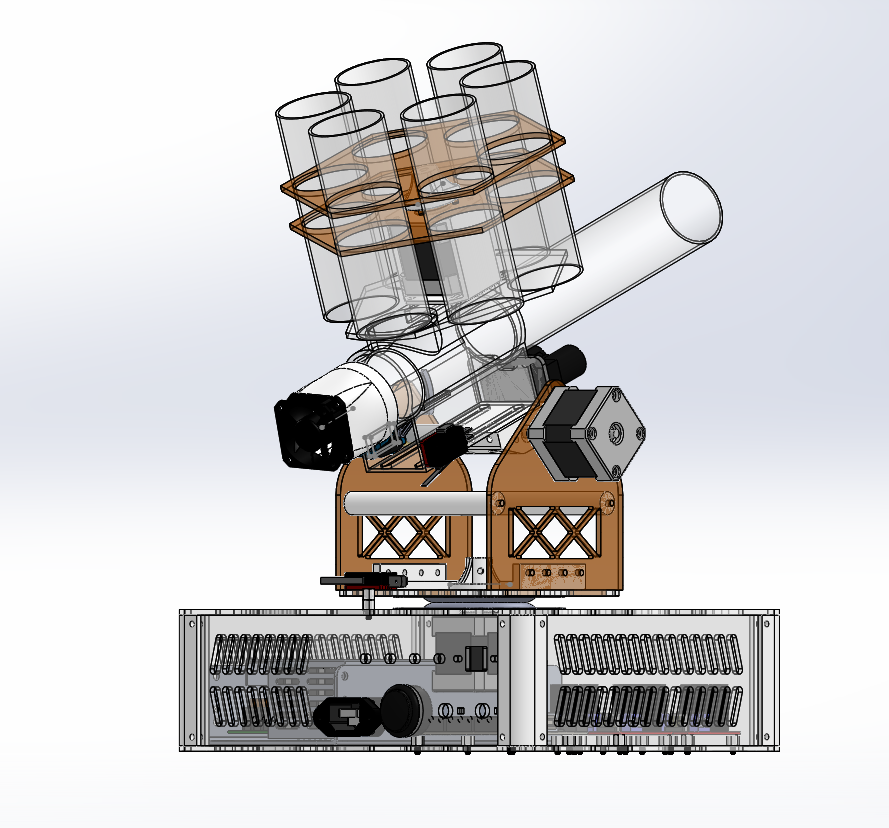
Previously, we had planned on using a gravity fed, revolver style method for loading the ping pong balls into the barrel. But we found that there was a significant loss of power when test firing with the hole on top open, and the robot could only fire a ball halfway across the table at full power to the fan. We considered incorporating a servo actuated lid into the design for the revolver or adding additional "blank" tubes that would act as lids in between the actual tubes, but in the end we decided to go for a different approach, using two tubes that run parallel to the barrel to hold the ping pong balls.


We also did some testing for accuracy, and added a strip of electrical tape to the bottom of the barrel to give the ball some topspin.


After working over the weekend we have most of the mechanical frame assembled, and we verified that we could move the stepper motors and stop them with the limit switches.