After spending a lot of time wiring and rewiring the robot, we are getting closer to being completely out of "hardware mode" and can spend more time on the software end of things.
We've added some sensors to the loading system for detecting the position of a ping pong ball, which has made the loading process much more simple to code.
We've also started working on a GUI for displaying data from the robot and controlling it remotely using Python and PyQt.
There's still definitely a lot more work to be done, but things are coming together well right now.
Previously, we had planned on using a gravity fed, revolver style method for loading the ping pong balls into the barrel. But we found that there was a significant loss of power when test firing with the hole on top open, and the robot could only fire a ball halfway across the table at full power to the fan. We considered incorporating a servo actuated lid into the design for the revolver or adding additional "blank" tubes that would act as lids in between the actual tubes, but in the end we decided to go for a different approach, using two tubes that run parallel to the barrel to hold the ping pong balls.
We also did some testing for accuracy, and added a strip of electrical tape to the bottom of the barrel to give the ball some topspin.
After working over the weekend we have most of the mechanical frame assembled, and we verified that we could move the stepper motors and stop them with the limit switches.
In my junior year at OSU I found myself needing a mill frequently and had no way to access one without driving several hours. I came up with a small, lightweight solution to the problem by attaching a small xy table to my drill press and using an aluminum miter jig as a clamp. The results are passable for light duty work, but the setup time isn't the best and you have to feed the pieces slowly in order to keep everything from vibrating too much.
In winter term of my senior year at OSU I had someone come in to TekBots with a homemade water cooling pump system in a state of disrepair used for cooling a reactor in a research lab and offered to pay me to make it functional again. I replaced the old control system with my own and laser cut a new top plate with a printed label inside and panel mounted switches and potentiometers (the original system had trimmer pots on protoboard). He was pleased enough with my work that he has since come back to me asking me to make three larger systems that each have six pumps. I've built him a working prototype and the parts for the rest of the systems are ordered and waiting for me to design a case to hold them.
Several months ago I experimented a bit with smoothing 3d printed ABS parts with Acetone. I tried using an acetone pen used for removing fingernail polish with little (no) success. I then tried using a vapor bath approach, by putting a small pool of acetone in the bottom of a glass jar and holding the part above it by some string. After 5-10 minutes there was some slight smoothing, but not at the level I was hoping for. I then bought a cheap electric stove to heat the acetone in the jar and had much better results. However, even on the very lowest setting the stove was hot enough to boil the acetone almost instantly. This had the effect of smoothing the part in 5-10 seconds but even using the setup outside I wasn't very comfortable about the fumes I was releasing. This definitely falls under the category of "do not try this at home", and especially not inside.
During the summer of my internship at Tektronix my roommate was interning at Intel working on a rover. I can't say much about it, but I can show you the chassis frame that I made for him (including the custom shocks I made).
The motors that my friend ended up with were much smaller than the ones I had designed the arms for
As I only need a few more credits to receive my Bachelors degree in Electrical Engineering, I thought I'd take the applied robotics course, where students work in teams of 3 to create a robot to play a game against the other teams by the end of the term. This year's game is Beerpong, and we've been busy trying to come up with the best way to locate the cups and launch ping pong balls accurately.
We decided to go with a pan/tilt design for aiming using NEMA 17 stepper motors that will allow us to attach many different types of firing mechanisms so we can get good test data for different methods as we progress, and chose a standard spacing for the mounting holes to let us fit 80 20 extruded aluminum if we wanted. Our method for locating the cups is to use the (relatively) cheap LIDAR-Lite module mounted to the turret which will scan back and forth, allowing us to find the closest cup. The other teams that we have talked to are all planning on using a webcam or a Kinect camera and OpenCV for detecting the cups, but we would like to avoid the additional complication of using a computer and are opting to instead keep everything on an embedded system (plus the LIDAR-Lite already has example code for the Arduino written for it, which will dramatically cut down on the time it takes to develop the low level code for our system. We chose to run with the Arduino Mega 2560 so we could make use of the existing libraries for driving stepper motors, servos and other modules that we may decide to use (and you can't ever have too many UART channels).
We verified the pan/tilt design by cutting it out of cardboard before moving to acrylic:
After putting in a solid weekend of work we had a prototype version to test:
Not long after we got that method working we were discussing with another group and found that they were getting more consistent results by simply attaching a fan to the end of their barrel and blowing the ping pong ball through the barrel. We had to test for ourselves, and printed a test adapter to fit a 38mm fan that I had which is an absolute champ for it's size.
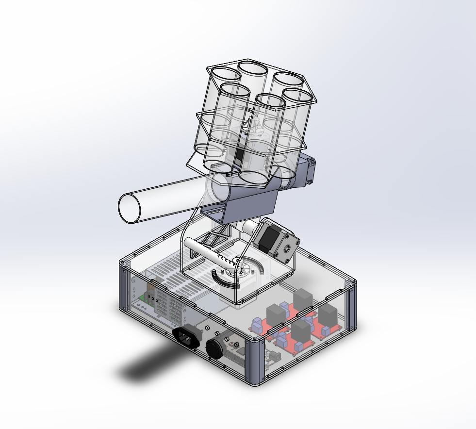
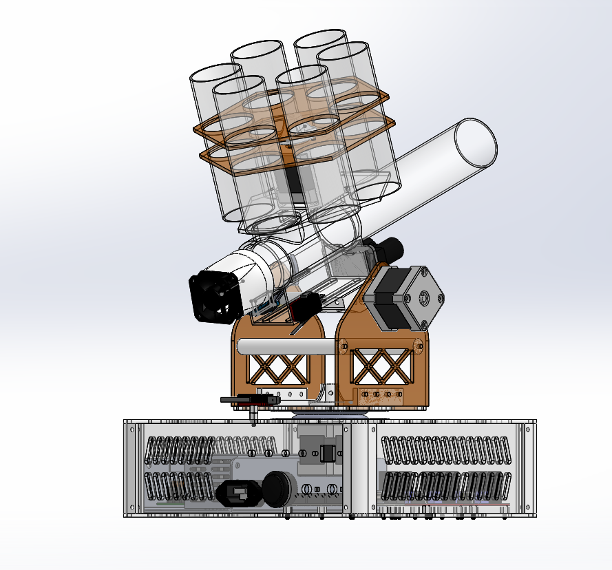
Our latest design will involve a revolving set of tubes for holding the 18 ping pong balls we're allowed while keeping us within the 24"x24"x72" size restriction, and we are aiming at getting a finalized design done by the beginning of next week. We have also ordered some polycarbonate tubing to ensure a more consistent inner diameter than the schedule 40 PVC pipe we were using before (and it also has the benefit of being transparent).
This is the rough approach that we want to go for, we are planning on some improvements over this design including tilting the tubes for the ball holders to a 45 degree angle to make it more compact.
We are almost at the end of the third week of the term, and we will need to have the robot finished for the competition during finals week (week 11).
I wasn't satisfied with the performance of the glass bed on my Press-- nothing would stick to it. I've seen a bunch of people say to use hair spray or a glue stick, but that's a band-aid solution to me. None of the other 3d printers I've used have needed any special treatments done to the bed to make them work, and I wanted the same to be true for the Press.
I decided to try the same method of print bed as the Up! Mini 3d printer, which is a perforated board of FR4 (the stuff they use to make a lot of PCBs with). I've used the Up! Mini and have been impressed with it's "plug-and-play-ness".
I found a 10"x10" unclad FR4 Perf Board on DigiKey that looked promising, and once I trimmed off a side so it was the width of the original bed it slid right in to the printer. I put the original glass bed in the bottom of the printer for safekeeping.
After running the Z-Axis calibration I was able to print out a test part from another project and it came out the first try.
There is definitely more work to be done with the settings for the support material, but for now I can at least print basic parts.
Update: Here's a video showing how easy it is to remove parts from the perf board, and a photo of the finished test part. These ridges come off very easily and leave a smooth surface with a knife, or if you have rafting layers it becomes a non-issue.
Update 3/17/2015:
After spending more time calibrating the printer and removing the top propriatary spool holder I was able to print a larger part with good results. I also added binder clips to the front corners to keep them from lifting up.
As you can see the HIPS holds to the build plate well enough to prevent curling but comes off much more easily than the standard filament from Stratasys.
There's a *very* long list of things that I have yet to update on the blog, but this is something I'm going to stay on top of.
I recently found out from the Have Blue website that there is a way to flash the EEPROMS from scratch with a Raspberry Pi for the Stratasys 3d printer cartridges on the Dimension BST series printers. This means that you can refill the printer with 3rd party filament without modifying the printer, something that is going to become very useful since Stratasys is dropping support for the BST 1200 series on June 30th, 2015. I had already modified the 3d printer at my school in order to make student printing affordable, but this method requires the printer to be reset after reloading the cartridge EEPROM, which is a problem if a cartridge runs out during a print and all of the chips are empty.
After seeing all of this I thought that while people who already had EEPROMs from used cartridges would still be able to use the printers, those who had returned their used cartridges for a discount wouldn't be able to use this workaround without paying through the nose for a used cartridge, which would only continue to become more expensive and scarce. So I went to a friend of mine who is a whiz at making PCBs and asked if he could make a board for the EEPROMs that could substitute the originals. Since the circuit is only two pieces and the layout is straightforward he was able to make it in less than an hour in Eagle. Using OSH Park to make the boards gets you three PCBs for $6.65 (while the screenshot below makes it appear that the notch in the middle is missing it is present in the board outline). A suitable 4.7k ohm resistor can easily be found on DigiKey.
However, the original Maxim DS2433 EEPROM chip has been replaced with the DS24B33. The previous link contains details about the differences between the chips. Of particular note is the increased max current draw from 500 micro amps to 2 milliamps and the increase in recovery time. This may make the chip unusable with the Stratasys printers. DigiKey does have the DS24B33 available if you would like to try this chip. I will order one and will post results when I have them. It is also possible that if the new chip does not work out of the box there is a config file for the 1-wire interface on the Stratasys that could be edited to make it compatible.
The Eagle board and schematic files can be downloaded here. Note that these files may not be used for commercial sale and all use is AT YOUR OWN RISK. While the boards have been ordered from OSH Park and the schematic is very simple this board has not been tested and verified as of 1/14/2015.
Update 5/11/2015:
It has been a while since I've had time to work on this project. The PCBs came in the mail, and I've stuffed the boards with the parts. Unfortunately I wasn't able to communicate with the new chip using the bus pirate, although I'm not sure if this is because of a hardware problem or because the script I was using had an error trying to read a cartridge from a blank chip. Here is a side by side comparison between the original PCB (green) and the replacement (purple):


.jpg)


.PNG)